
David Bridgeman-Sutton follows up the story of the invention of the Barker lever to see how other builders have improved on the design
Bettering Barker
Henry — “Father” — Willis had reservations about pneumatic and electric actions, although his firm made considerable use of these. He was aware that their “on/off” effect robbed players of fine control over pallets. The Barker lever, which he used extensively, suffered from this defect.
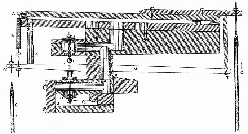
Figure 1 is a drawing from the original patent application; this comes, with permission from
Willis organs.
His inventive son, Vincent, set out to devise an action that overcame this problem. The result was the “floating lever”, patented in 1884.
From the description given there, it will be seen that it is a modified Barker lever* (see previous page) providing servo assistance to tracker action.
Very effective it is, too, though few were made and fewer remain. Its lack of commercial success was probably due to two factors — fashion and cost. New methods, especially those employing electricity, were demanded everywhere, and nothing could have been less new than tracker action, however modified — and heavy tracker actions had, by then, a justifiably bad name.
Also, tracker actions are far more expensive to make than other forms. Electric wires and pneumatic tubes, being flexible, are easily run between console and windchests. With tracker action, every link and every change of direction has to be specially designed and very accurately made by craftsmen.
|
Fig. 2 shows just one component — a roller board, of which there will be at least one to each division.
Its function is to align the mechanical connections of the keys with those to windchests — which latter are inevitably much wider than keyboards and usually have pipes in non-chromatic order — as well as other complications! This roller board is in the Christchurch Town Hall Rieger. The rollers themselves are of light alloy construction. Iron, which was undesirably heavy, was used in many older organs; this, in turn had replaced wood, which tended to flex slightly, thus introducing an undesirable “springiness” to the touch. |
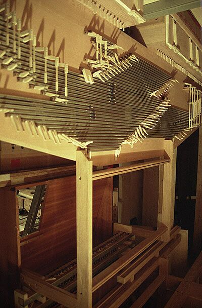
Pic. 2: Christchurch Rieger roller board
|
The idea of servo-assistance in organs crossed the Atlantic after a visit to England by Ernest Skinner, who wanted to retain mechanical linkage between swell pedal and shutters (shades) in some of the very large instruments he was building.
More recently C.B.Fisk, builders in Gloucester, Massachusetts, developed their own servo-pneumatic lever, similar in principle to that of Willis. This has been applied to a number of instruments including that in Lausanne (Switzerland) Cathedral. Many of these are large instruments in which the use of unassisted tracker action would have been impracticable.
The present firm of Henry Willis is said to be introducing an improved form of the floating lever.
Pic. 3:
|
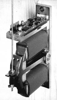
A digital age approach has been pioneered by Eltec in Italy
This employs an electronic sensor with 128 “gradations” to each key. As a key is pressed or released its position is transmitted to a unit containing a pair of electromagnets as in figure 3. The respective powers of these are balanced so that the pole piece — to which the pallet is connected — reproduces the key movement. More information about this would be interesting. |
David Bridgeman-Sutton,
July 1, 2004
July 1, 2004
Thanks for information and help to David Wyld at Henry Willis and to Mark Newton at C B Fisk
Credits:
Picture 1: Henry Willis
Picture 2: Jenny Setchell.
Picture 3: Jessye Beecham
Picture 1: Henry Willis
Picture 2: Jenny Setchell.
Picture 3: Jessye Beecham
